Main Menu
Useful Links
Contact us
Follow us
© 2025 Omnitron Systems Technology, Inc. All Rights Reserved. | Privacy Policy
ADDITIONAL FEATURES
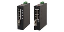
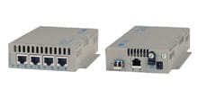
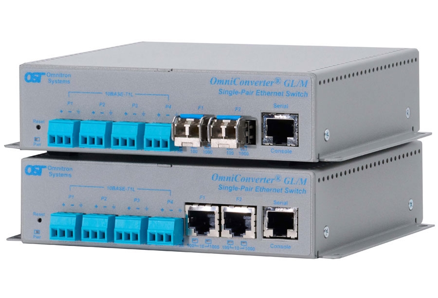
The OmniConverter GL/M is a managed compact gigabit Ethernet switch that features copper or fiber uplink ports and four single-pair 10BASE-T1L Ethernet copper user ports.
The Single Pair Ethernet switch features four IEEE 802.3cg compliant 10BASE-T1L 3-pin SPE terminal ports or IEC 63171-2 SPE ports and two 10/100/1000 RJ-45 or 100/1000 fiber uplink ports.
The OmniConverter GL/M is a standard Layer 2 Ethernet switch that forwards frames to any port based on their MAC address.
The switch supports Dual Device mode, Directed Switch mode and Protected Uplinks.
Dual Device mode enables the module to operate as two independent and isolated Ethernet switches. In Dual Device mode, the GL/M provides separate and independent data traffic paths between the two uplink ports and four user ports.
Directed Switch mode directs multicast traffic (such as video) only to the appropriate uplink port, preventing the multicast video traffic from flooding other network ports.
The switch supports protected uplinks using industrial ring Media Redundancy Protocol (MRP) or Spanning Tree Protocol or Redundant uplinks for high availability industrial network applications.
For daisy-chain applications, the second uplink port can be used to cascade multiple switches.
The mode of operation can be configured using easily accessible DIP-switches or using Web, Telnet, SSH, SNMPv1/v2c/v3 or Serial Console management interfaces. IPv4 and IPv6 are supported on the switches. These management interfaces provide access to filtering and security options, such as, broadcast storm prevention, IGMP, IEEE 802.1x, RADIUS, TACACS+ and Access Control Lists. Email notification and alarm reporting is provided.
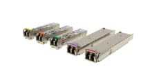
The switch is available with Small Form Pluggable (SFP) transceiver receptacle ports or 10/100/1000 RJ-45 ports. The SFP ports support 10/100/1000BASE-T and 1000BASE-T copper transceivers and 100Mbps and 1000Mbps standard, CWDM and DWDM fiber transceivers in a variety of distances and fiber types.
The switch can be wall mounted, rack mounted using a shelf (8260-0) or DIN-rail mounted using the DIN-rail mounting clips (8251-0). The switch is available with an external 100 to 240V AC power adapter or with a DC terminal connector.
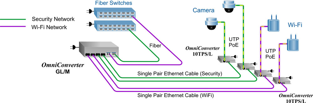
Dual Device Mode Application
This Dual Device feature is extremely useful when two isolated networks domains share a single network distribution location.
The example below depicts a scenario where a surveillance security (green) network and a Wi-Fi (purple) network are sharing a single hub distribution location. Using the two uplinks and the Dual Device mode facilitates using a single switch driving both the Cameras and the Wi-Fi Access Points across SPE cabling while maintaining isolation between the networks. At the far end, OmniConverter 10TPS/L modules are used to power the Cameras and Access Points.
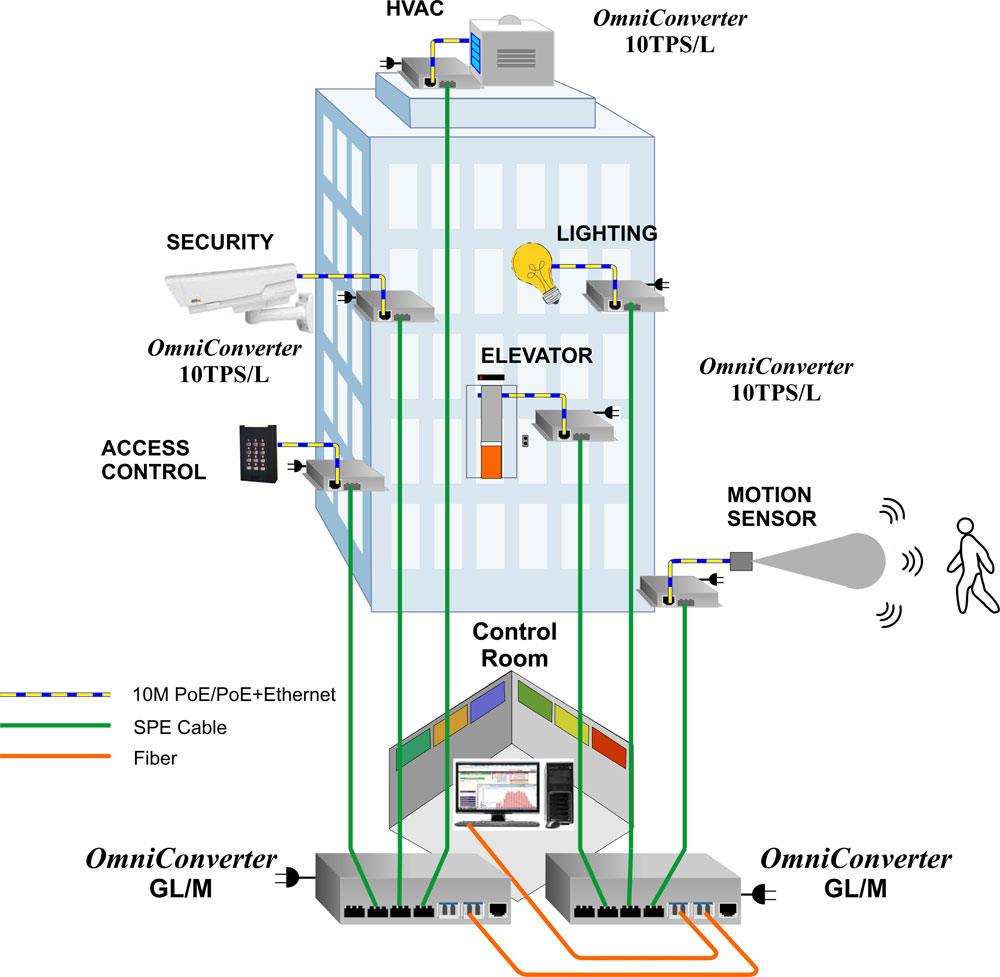
Building Automation Application
This example shows a Building Automation application using an OmniConverter GL/M and 10TPS/L modules to connect building systems back to a centralized control room. Each building system is powered by PoE/PoE+ from the OmniConverter 10TPS/L modules. Systems controlled by the OmniConverter modules include Motion Detection, Lighting, Elevator Control, Access Control to Floors, Security Surveillance and HVAC.
| Description |
OmniConverter® GL/M 10T/T1L to 100/1000 Fiber or 10/100/1000 Copper Uplinks Managed Ethernet Switch |
|---|---|
| Standard Compliances |
IEEE 802.3, IEEE 802.3cg, IEEE 802.1Q, IEEE 802.1ad, IEEE 802.1ab, IEEE 802.1ax, IEEE 802.1w RSTP/MSTP, RFC 5424, RFC 4541, RFC 2710, IEC 624339-2, SMTP, SNTP, RADIUS, TACACS+, IEEE 802.1x |
| Regulatory Compliances (Pending) |
Safety: UL 62368-1, UL 60950-1, IEC 62368-1, IEC 60950-1, EN 62368-1, EN 60950-1, CAN/CSA C22.2 No. 62368-1-14, CAN/CSA C22.2 No. 60950-1, CE Mark, UKCA EMC: EN 55032/24 CE Emissions/Immunity, IEC 61000-6-4 Industrial Emissions, IEC 61000-6-2 Industrial Immunity EMI: CISPR 32, FCC 47 Part 15 Subpart B Class A EMS: IEC 61000-4-2 ESD: Contact: 6 kV; Air: 8 kV, IEC 61000-4-3 RS: 80 MHz to 1 GHz: 10 V/m, IEC 61000-4-4 EFT: Power: 2 kV; Signal: 1 kV (DC models), IEC 61000-4-4 EFT: Power: 1 kV; Signal: 1 kV (AC models), IEC 61000-4-5 Surge: Power: 2 kV; Signal: 2 kV (DC models), IEC 61000-4-5 Surge: Power: 1 kV Line/Line; 2 kV Line/Gnd; Signal: 2 kV (AC models), IEC 61000-4-6 CS: Signal: 10 V, IEC 61000-4-8 (Magnetic Field) 30A/m, IEC 61000-4-11 (Voltage Dips, interrupts) IP Rating: IP20 Protection ACT: TAA, BAA, NDAA |
| Environmental | REACH, RoHS and WEEE |
| Management |
IPv4 and IPv6 address Web, Telnet, SSH, SNMPv1/v2c/v3 In-Band management via Ethernet port Out-of-band management via serial port |
| Frame Size |
10BASE-T1L: Up to 2,048 bytes RJ-45: Up to 10,240 bytes SFP: 100M - up to 2,048 bytes 1000M - up to 10,240 bytes |
| Port Types |
10BASE-T1L: 3-Pin SPE Terminal connector or IEC 63171-2 SPE connector RJ-45: 10/100/1000BASE-T SFP: 10/100/1000BASE-T SGMII or 1000BASE-T SERDES Copper Transceiver, 100BASE-X or 1000BASE-X Fiber Transceiver |
| Cable Types |
10BASE-T1L: Single-Pair Ethernet (SPE) cable, IEC 61156-13 (fixed) or IEC 61156-14 (flexible) 18AWG cable or better RJ-45: EIA/TIA 568A/B, Cat 5 UTP and higher Fiber: Multimode: 50/125, 62.5/125µm Single-mode: 9/125µm |
|
AC Power Requirements (Models with AC/DC Adapters) |
100 - 240VAC/50 - 60Hz 0.9A max at 115VAC; 0.5A max at 230VAC |
|
DC Power Requirements (Models with DC Terminals) |
+12 to +58VDC; 0.66A @ 12VDC; 2 Pin Terminal (isolated) |
|
Dimensions (W x D x H) |
6.28” x 5.2” x 1.5” (159.5 mm x 132.1 mm x 38.1 mm) |
| Weight |
Module Only: 1.5 lb.; 720 grams Module with AC/DC Adapter: 2.0 lbs.; 913 grams |
| Operating Temperature |
Commercial: 0 to 50°C Wide: -40 to 60°C (-20°C AC cold start) Extended: -40 to 75°C (-20°C AC cold start) Storage: -40 to 80°C |
| Humidity | 5 to 95% (non-condensing) |
| Altitude | -100m to 4,000m (operational) |
| MTBF (hours) |
Module Only: 207,000 AC/DC Adapter: 100,000 |
| Warranty | 5 year product warranty with 24/7/365 free Technical Support and 2 year AC power adapter warranty |
| Model Number | Description |
|---|---|
| 2910-0-4c-pt | 4 x 10BASE-T1L + 2 x 100/1000 SFP Ports |
| 2910-1-4c-pt | 4 x 10BASE-T1L + 2 x 10/100/1000 RJ-45 Ports |
| 0 = 3-pin SPE Terminal Connector |
| 2 = IEC 63171-2 SPE Connector |
| 1 = External AC/DC Adapter, 100 - 240 VAC included, with US Power Cord |
| 2 = External AC/DC Adapter, 100 - 240 VAC included, No Power Cord |
| 8 = External AC/DC Adapter, 100 - 240 VAC included, PS JET/PSE Certified, with Japanese Power Cord |
| 9 = Direct DC 2 pin terminal connector, no AC/DC power adapter |
| <leave blank> = Commercial temperature (0 to 50°C) |
| W = Wide temperature (-40 to 60°C) |
| Z = Extended temperature (-40 to 75°C) |
| Model Number | Description |
| 8251-0 | DIN-Rail Mounting Clip |
| 8260-0 | 19” rack mount shelf (up to 2 modules) |
Main Menu
Useful Links
Contact us
Follow us
© 2025 Omnitron Systems Technology, Inc. All Rights Reserved. | Privacy Policy
