- Description
- Features
- Specifications
- Applications
- Ordering
- Documents
The iConverter T1/E1 MUX/M multiplexes up to sixteen T1 or E1 circuits and one 10/100/1000 Ethernet service onto a 1000Mbps fiber optic transport link, and features remote management testing and configuration capabilities.
The iConverter T1/E1 MUX/M operates in a back-to-back configuration, and can be used in applications such as multiple T1/E1 extension, mobile backhaul and building-to-building PBX connectivity.
The T1/E1 copper interfaces are available in 4, 8, 12 or 16 RJ-48 port configurations for balanced T1/E1 applications. Optional adapter cables are available to convert each RJ-48 interface to a BNC interface for unbalanced E1 transport applications.
Additional hot-swappable 4-Port T1/E1 MUX modules can be installed to increase system capacity up to 16 T1/E1 ports maximum per 1U (1.75 inch) chassis.
The T1/E1 MUX/M is available with fixed-fiber or Small Form Pluggable (SFP) transceivers, enabling easy adaptability to different fiber types, distances and wavelengths. The T1/E1 MUX/M supports multimode, single-mode dual fiber and single-mode single-fiber in standard (850nm, 1310nm and 1550nm) and CWDM/DWDM wavelengths.
The T1/E1 MUX/M features user-selectable local loop-back on both the copper and fiber ports, remote fiber loop-back and circuit test modes. These features facilitate testing of the remote unit, and minimize the need for test equipment and support personnel. Alarm relays and LEDs provide fault notification for loss of power, LOS and AIS.
Configuration of T1/E1 line codes, line build-out, loopbacks and circuit test is accomplished via local serial port, Telnet, SNMP, or DIP-switches.
The 1U high iConverter T1/E1 MUX/M chassis can be mounted in a 19-inch or 23-inch rack and features two load-sharing power supplies. It supports hot-swappable universal AC, 24VDC or 48VDC power supplies for power redundancy.
2420-0-11, 2420-0-12, 2420-0-13, 2420-0-14, 2420-0-15, 2420-0-16, 2420-0-21, 2420-0-22, 2420-0-23, 2420-0-24, 2420-0-25, 2420-0-26, 2420-0-31, 2420-0-32, 2420-0-33, 2420-0-34, 2420-0-35, 2420-0-36, 2420-0-41, 2420-0-42, 2420-0-43, 2420-0-44, 2420-0-45, 2420-0-46, 2421-1-11, 2421-1-12, 2421-1-13, 2421-1-14, 2421-1-15, 2421-1-16, 2421-1-21, 2421-1-22, 2421-1-23, 2421-1-24, 2421-1-25, 2421-1-26, 2421-1-31, 2421-1-32, 2421-1-33, 2421-1-34, 2421-1-35, 2421-1-36, 2421-1-41, 2421-1-42, 2421-1-43, 2421-1-44, 2421-1-45, 2421-1-46, 2422-0-11, 2422-0-12, 2422-0-13, 2422-0-14, 2422-0-15, 2422-0-16, 2422-0-21, 2422-0-22, 2422-0-23, 2422-0-24, 2422-0-25, 2422-0-26, 2422-0-31, 2422-0-32, 2422-0-33, 2422-0-34, 2422-0-35, 2422-0-36, 2422-0-41, 2422-0-42, 2422-0-43, 2422-0-44, 2422-0-45, 2422-0-46, 2423-1-11, 2423-1-12, 2423-1-13, 2423-1-14, 2423-1-15, 2423-1-16, 2423-1-21, 2423-1-22, 2423-1-23, 2423-1-24, 2423-1-25, 2423-1-26, 2423-1-31, 2423-1-32, 2423-1-33, 2423-1-34, 2423-1-35, 2423-1-36, 2423-1-41, 2423-1-42, 2423-1-43, 2423-1-44, 2423-1-45, 2423-1-46, 2423-2-11, 2423-2-12, 2423-2-13, 2423-2-14, 2423-2-15, 2423-2-16, 2423-2-21, 2423-2-22, 2423-2-23, 2423-2-24, 2423-2-25, 2423-2-26, 2423-2-31, 2423-2-32, 2423-2-33, 2423-2-34, 2423-2-35, 2423-2-36, 2423-2-41, 2423-2-42, 2423-2-43, 2423-2-44, 2423-2-45, 2423-2-46, 2423-3-11, 2423-3-12, 2423-3-13, 2423-3-14, 2423-3-15, 2423-3-16, 2423-3-21, 2423-3-22, 2423-3-23, 2423-3-24, 2423-3-25, 2423-3-26, 2423-3-31, 2423-3-32, 2423-3-33, 2423-3-34, 2423-3-35, 2423-3-36, 2423-3-41, 2423-3-42, 2423-3-43, 2423-3-44, 2423-3-45, 2423-3-46, 2423-4-11, 2423-4-12, 2423-4-13, 2423-4-14, 2423-4-15, 2423-4-16, 2423-4-21, 2423-4-22, 2423-4-23, 2423-4-24, 2423-4-25, 2423-4-26, 2423-4-31, 2423-4-32, 2423-4-33, 2423-4-34, 2423-4-35, 2423-4-36, 2423-4-41, 2423-4-42, 2423-4-43, 2423-4-44, 2423-4-45, 2423-4-46, 2423-5-11, 2423-5-12, 2423-5-13, 2423-5-14, 2423-5-15, 2423-5-16, 2423-5-21, 2423-5-22, 2423-5-23, 2423-5-24, 2423-5-25, 2423-5-26, 2423-5-31, 2423-5-32, 2423-5-33, 2423-5-34, 2423-5-35, 2423-5-36, 2423-5-41, 2423-5-42, 2423-5-43, 2423-5-44, 2423-5-45, 2423-5-46, 2430-1-11, 2430-1-12, 2430-1-13, 2430-1-14, 2430-1-15, 2430-1-16, 2430-1-21, 2430-1-22, 2430-1-23, 2430-1-24, 2430-1-25, 2430-1-26, 2430-1-31, 2430-1-32, 2430-1-33, 2430-1-34, 2430-1-35, 2430-1-36, 2430-1-41, 2430-1-42, 2430-1-43, 2430-1-44, 2430-1-45, 2430-1-46, 2431-1-11, 2431-1-12, 2431-1-13, 2431-1-14, 2431-1-15, 2431-1-16, 2431-1-21, 2431-1-22, 2431-1-23, 2431-1-24, 2431-1-25, 2431-1-26, 2431-1-31, 2431-1-32, 2431-1-33, 2431-1-34, 2431-1-35, 2431-1-36, 2431-1-41, 2431-1-42, 2431-1-43, 2431-1-44, 2431-1-45, 2431-1-46, 2430-2-11, 2430-2-12, 2430-2-14, 2430-2-15, 2430-2-16, 2430-2-21, 2430-2-22, 2430-2-23, 2430-2-24, 2430-2-25, 2430-2-26, 2430-2-31, 2430-2-32, 2430-2-33, 2430-2-34, 2430-2-35, 2430-2-36, 2430-2-41, 2430-2-42, 2430-2-43, 2430-2-44, 2430-2-45, 2430-2-46, 2431-2-11, 2431-2-12, 2431-2-13, 2431-2-14, 2431-2-15, 2431-2-16, 2431-2-21, 2431-2-22, 2431-2-23, 2431-2-24, 2431-2-25, 2431-2-26, 2431-2-31, 2431-2-32, 2431-2-33, 2431-2-34, 2431-2-35, 2431-2-36, 2431-2-41, 2431-2-42, 2431-2-43, 2431-2-44, 2431-2-45, 2431-2-46, 2439-0-11, 2439-0-12, 2439-0-13, 2439-0-14, 2439-0-15, 2439-0-16, 2439-0-21, 2439-0-22, 2439-0-23, 2439-0-24, 2439-0-25, 2439-0-26, 2439-0-31, 2439-0-32, 2439-0-33, 2439-0-34, 2439-0-35, 2439-0-36, 2439-0-41, 2439-0-42, 2439-0-43, 2439-0-44, 2439-0-45, 2439-0-46,IE-IMCV-T1-MUX/4 857-18110,RAD Optimux 45 28T1 Over Fiber SM Multiplexer ,SKU: OP45B28XACRST13L
|
|||||||||||||||||||||||||||||||||||||||||||||||||||||||
- Multiplexes up to sixteen independent T1 or E1 copper circuits onto one fiber link
- 10/100/1000 copper Ethernet service multiplexed with T1/E1 circuits
- 1000Mbps fixed fiber transceiver or Small Form Pluggable (SFP), in standard and CWDM/DWDM wavelengths
- Supports multimode, single-mode dual fiber and single-mode single-fiber
- Supports AMI, B8ZS and HDB3 line codes
- Easy configuration of T1/E1 line codes and line build-out
- Configurable alarm relay contacts for audio/visual fault notification
- Supports local and remote fiber and copper loop-back modes
- Remotely-managed configuration and testing enable rapid deployment
- Management via local serial port, Telnet, or SNMP
- SNMP management via NetOutlook® provides real-time port and module status information, configuration and trap notification
- Commercial (0 to 50° C ) and wide (-40 to 60° C) operating temperature ranges
- TAA, BAA and NDAA Compliant, and Made in the USA
- Lifetime Warranty and free 24/7 Technical Support
Mobile Backhaul
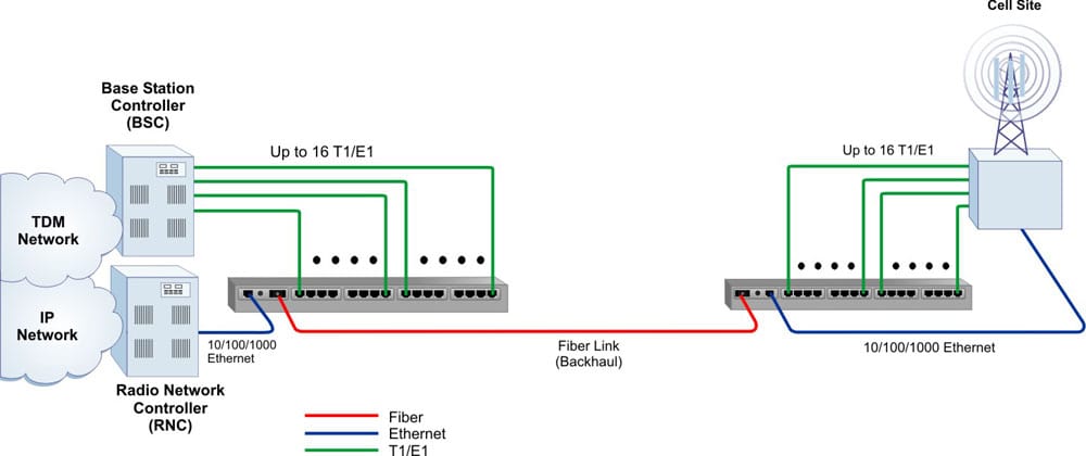
Mobile Backhaul The following application shows an example of the iConverter T1/E1 MUX/M used in a hybrid TDM/Ethernet transport network.
A wireless service provider has enhanced their network to support 3G/4G services. The new equipment uses Ethernet for backhaul at the Cell Site, while their existing legacy 2G equipment uses TDM (T1) for backhaul.
At the Base Station Controller (BSC) and Radio Network Controller (RNC), a iConverter T1/E1 MUX/M is installed to extend the TDM and IP Networks to the Cell Site. The service provider is able to multiplex up to 16 T1/E1 circuits and one 10/100/1000 Ethernet service on a common fiber link.
The fiber carries the multiplexed traffic to a second iConverter T1/E1 MUX/M installed at the Cell Site where the T1/E1 circuits and Ethernet service provides connectivity to the equipment at the site.
Step 1: Choose the Base Part Number (xxxx-x-mpt)
|
Fiber
Type |
Distance
|
Connector Types
|
Tx / Rx
Lambda (nm) |
Min. Tx
Power (dBm) |
Max. Tx
Power (dBm) |
Min. Rx
Power (dBm) |
Max. Rx
Power (dBm) |
Min.
Attenuation (dB) |
Link
Budget (dB) | ||
|---|---|---|---|---|---|---|---|---|---|---|---|
|
ST
|
SC
|
SFP
| |||||||||
|
-
|
-
|
-
|
-
|
2439-0-mpt
|
-
|
-
|
-
|
-
|
-
|
-
|
-
|
|
MM/DF
|
220/550m1
|
2420-0-mpt
|
2422-0-mpt
|
-
|
850/850
|
-10
|
-4
|
-17
|
-3
|
-
|
7
|
|
SM/DF
|
12km
|
2421-1-mpt
|
2423-1-mpt
|
-
|
1310/1310
|
-9.5
|
-3
|
-19.5
|
-3
|
-
|
10
|
|
SM/DF
|
34km
|
-
|
2423-2-mpt
|
-
|
1310/1310
|
-5
|
0
|
-23
|
-3
|
3
|
18
|
|
SM/DF
|
80km
|
-
|
2423-3-mpt
|
-
|
1550/1550
|
-5
|
0
|
-23
|
-3
|
3
|
18
|
|
SM/DF
|
110km
|
-
|
2423-4-mpt
|
-
|
1550/1550
|
0
|
5
|
-24
|
-3
|
8
|
24
|
|
SM/DF
|
140km
|
-
|
2423-5-mpt
|
-
|
1550/150
|
2
|
5
|
-28
|
-8
|
13
|
30
|
|
SM/SF2
|
20km
|
-
|
2430-1-mpt
|
-
|
1310/1550
|
-9.5
|
-3
|
-20
|
-3
|
-
|
10.5
|
|
SM/SF2
|
20km
|
-
|
2431-1-mpt
|
-
|
1550/1310
|
-9.5
|
-3
|
-20
|
-3
|
-
|
10.5
|
|
SM/SF2
|
40km
|
-
|
2430-2-mpt
|
-
|
1310/1550
|
-3
|
0
|
-20
|
-3
|
3
|
17
|
|
SM/SF2
|
40km
|
-
|
2431-2-mpt
|
-
|
1550/1310
|
-3
|
0
|
-20
|
-3
|
3
|
17
|
|
1 62.5/125µm, 100/140µm multimode fiber up to 220m. 50/125µm multimode fiber up to 550m.
2 When using single-fiber (SF) models, the Tx wavelength on one end has to match the Rx wavelength on the other
MM = Multimode, SM = Single-mode, DF = Dual Fiber, SF = Single-fiber
Contact Omnitron for other fiber options and operating temperature ranges. Order the appropriate SFPs separately. Visit the Omnitron Optical Transceivers web page.
|
|||||||||||
Step 2: Choose the number of MUX modules (xxxx-x-mpt)
| 1 = One 4-Port MUX Module (4 ports total) | ||
| 2 = Two 4-Port MUX Module (8 ports total) | ||
| 3 = Three 4-Port MUX Module (12 ports total) | ||
| 4 = Four 4-Port MUX Module (16 ports total) |
Step 3: Choose your Power Option (xxxx-x-mpt)
| 1 = One AC Power Supply, 100 to 240VAC 50/60Hz, with IEC 320 Socke | ||
| 2 = Two AC Power Supply, 100 to 240VAC 50/60Hz, with IEC 320 Socket | ||
| 3 = One 48VDC Power Supply, +/- 36 to 60VDC, with 3 Pin Terminal (isolated) | ||
| 4 = Two 48VDC Power Supply, +/- 36 to 60VDC, with 3 Pin Terminal (isolated) | ||
| 5 = One 24VDC Power Supply, +/- 18 to 36VDC, with 3 Pin Terminal (isolated) | ||
| 6 = Two 24VDC Power Supply, +/- 18 to 36VDC, with 3 Pin Terminal (isolated) |
Step 4: Choose an Operating Temperature Range (xxxx-x-mpt)
| <leave blank> = Commercial temperature (0 to 50°C) | ||
| W = Wide temperature (-40 to 60°C) |
|
Accessories
| |
|---|---|
|
Model Number
|
Description
|
|
8220-9
|
Spare AC Power Supply
|
|
8226-9
|
Spare 24VDC Power Supply
|
|
8225-9
|
Spare 48VDC Power Supply
|
|
8485-4
|
Spare 4-Port T1/E1 MUX Module
|
|
9140-3
|
RJ-48 to Coax Adapter Cable (3 meters)
|
|
9142-1
|
RJ-48 Alarm Breakout Cable
|
|
8092-2
|
23" (wide) Rack Mount Kit
|
iConverter T1/E1 MUX/M (Data Sheet)
iConverter T1/E1 MUX/M (User Manual)
Menu Driven Interface T1/E1 Multiplexers (User Manual)
2420-0-11, 2420-0-12, 2420-0-13, 2420-0-14, 2420-0-15, 2420-0-16, 2420-0-21, 2420-0-22, 2420-0-23, 2420-0-24, 2420-0-25, 2420-0-26, 2420-0-31, 2420-0-32, 2420-0-33, 2420-0-34, 2420-0-35, 2420-0-36, 2420-0-41, 2420-0-42, 2420-0-43, 2420-0-44, 2420-0-45, 2420-0-46, 2421-1-11, 2421-1-12, 2421-1-13, 2421-1-14, 2421-1-15, 2421-1-16, 2421-1-21, 2421-1-22, 2421-1-23, 2421-1-24, 2421-1-25, 2421-1-26, 2421-1-31, 2421-1-32, 2421-1-33, 2421-1-34, 2421-1-35, 2421-1-36, 2421-1-41, 2421-1-42, 2421-1-43, 2421-1-44, 2421-1-45, 2421-1-46, 2422-0-11, 2422-0-12, 2422-0-13, 2422-0-14, 2422-0-15, 2422-0-16, 2422-0-21, 2422-0-22, 2422-0-23, 2422-0-24, 2422-0-25, 2422-0-26, 2422-0-31, 2422-0-32, 2422-0-33, 2422-0-34, 2422-0-35, 2422-0-36, 2422-0-41, 2422-0-42, 2422-0-43, 2422-0-44, 2422-0-45, 2422-0-46, 2423-1-11, 2423-1-12, 2423-1-13, 2423-1-14, 2423-1-15, 2423-1-16, 2423-1-21, 2423-1-22, 2423-1-23, 2423-1-24, 2423-1-25, 2423-1-26, 2423-1-31, 2423-1-32, 2423-1-33, 2423-1-34, 2423-1-35, 2423-1-36, 2423-1-41, 2423-1-42, 2423-1-43, 2423-1-44, 2423-1-45, 2423-1-46, 2423-2-11, 2423-2-12, 2423-2-13, 2423-2-14, 2423-2-15, 2423-2-16, 2423-2-21, 2423-2-22, 2423-2-23, 2423-2-24, 2423-2-25, 2423-2-26, 2423-2-31, 2423-2-32, 2423-2-33, 2423-2-34, 2423-2-35, 2423-2-36, 2423-2-41, 2423-2-42, 2423-2-43, 2423-2-44, 2423-2-45, 2423-2-46, 2423-3-11, 2423-3-12, 2423-3-13, 2423-3-14, 2423-3-15, 2423-3-16, 2423-3-21, 2423-3-22, 2423-3-23, 2423-3-24, 2423-3-25, 2423-3-26, 2423-3-31, 2423-3-32, 2423-3-33, 2423-3-34, 2423-3-35, 2423-3-36, 2423-3-41, 2423-3-42, 2423-3-43, 2423-3-44, 2423-3-45, 2423-3-46, 2423-4-11, 2423-4-12, 2423-4-13, 2423-4-14, 2423-4-15, 2423-4-16, 2423-4-21, 2423-4-22, 2423-4-23, 2423-4-24, 2423-4-25, 2423-4-26, 2423-4-31, 2423-4-32, 2423-4-33, 2423-4-34, 2423-4-35, 2423-4-36, 2423-4-41, 2423-4-42, 2423-4-43, 2423-4-44, 2423-4-45, 2423-4-46, 2423-5-11, 2423-5-12, 2423-5-13, 2423-5-14, 2423-5-15, 2423-5-16, 2423-5-21, 2423-5-22, 2423-5-23, 2423-5-24, 2423-5-25, 2423-5-26, 2423-5-31, 2423-5-32, 2423-5-33, 2423-5-34, 2423-5-35, 2423-5-36, 2423-5-41, 2423-5-42, 2423-5-43, 2423-5-44, 2423-5-45, 2423-5-46, 2430-1-11, 2430-1-12, 2430-1-13, 2430-1-14, 2430-1-15, 2430-1-16, 2430-1-21, 2430-1-22, 2430-1-23, 2430-1-24, 2430-1-25, 2430-1-26, 2430-1-31, 2430-1-32, 2430-1-33, 2430-1-34, 2430-1-35, 2430-1-36, 2430-1-41, 2430-1-42, 2430-1-43, 2430-1-44, 2430-1-45, 2430-1-46, 2431-1-11, 2431-1-12, 2431-1-13, 2431-1-14, 2431-1-15, 2431-1-16, 2431-1-21, 2431-1-22, 2431-1-23, 2431-1-24, 2431-1-25, 2431-1-26, 2431-1-31, 2431-1-32, 2431-1-33, 2431-1-34, 2431-1-35, 2431-1-36, 2431-1-41, 2431-1-42, 2431-1-43, 2431-1-44, 2431-1-45, 2431-1-46, 2430-2-11, 2430-2-12, 2430-2-14, 2430-2-15, 2430-2-16, 2430-2-21, 2430-2-22, 2430-2-23, 2430-2-24, 2430-2-25, 2430-2-26, 2430-2-31, 2430-2-32, 2430-2-33, 2430-2-34, 2430-2-35, 2430-2-36, 2430-2-41, 2430-2-42, 2430-2-43, 2430-2-44, 2430-2-45, 2430-2-46, 2431-2-11, 2431-2-12, 2431-2-13, 2431-2-14, 2431-2-15, 2431-2-16, 2431-2-21, 2431-2-22, 2431-2-23, 2431-2-24, 2431-2-25, 2431-2-26, 2431-2-31, 2431-2-32, 2431-2-33, 2431-2-34, 2431-2-35, 2431-2-36, 2431-2-41, 2431-2-42, 2431-2-43, 2431-2-44, 2431-2-45, 2431-2-46, 2439-0-11, 2439-0-12, 2439-0-13, 2439-0-14, 2439-0-15, 2439-0-16, 2439-0-21, 2439-0-22, 2439-0-23, 2439-0-24, 2439-0-25, 2439-0-26, 2439-0-31, 2439-0-32, 2439-0-33, 2439-0-34, 2439-0-35, 2439-0-36, 2439-0-41, 2439-0-42, 2439-0-43, 2439-0-44, 2439-0-45, 2439-0-46,IE-IMCV-T1-MUX/4 857-18110,RAD Optimux 45 28T1 Over Fiber SM Multiplexer ,SKU: OP45B28XACRST13L
