- Description
- Features
- Specifications
- Applications
- Ordering
- Documents
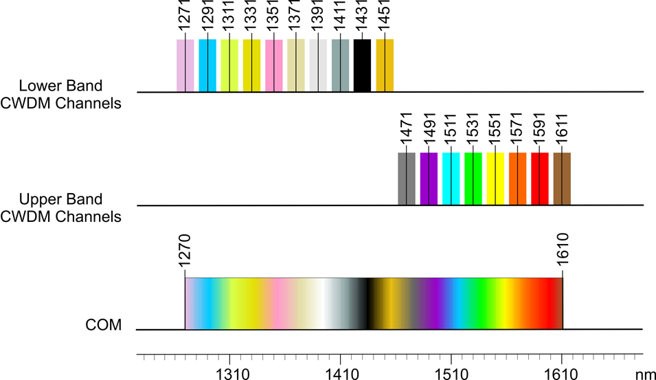
iConverter Single-Fiber Course Wave Division Multiplexing (CWDM) modules provide a flexible and cost-effective solution for increasing the fiber capacity of single fiber networks. CWDM over single-fiber increases network bandwidth capacity by enabling multiple wavelengths, or data channels that carry independent services over existing fiber infrastructure. Up to eight separate data channels can be transported on a single fiber link with iConverter Single-Fiber CWDM modules.
The iConverter CWDM/X and CWDM/AD single-fiber modules are protocol and rate transparent allowing different services up to 10Gbps to be transported across the same common fiber link. The single-fiber modules support dual fiber Channel Ports and single-fiber Common Port connections. Each fiber strand on the Channel Port supports a different wavelength, one wavelength for transmit (TX) and a different wavelength for receive (RX).
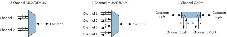
Single-Fiber CWDM/X Multiplexer/Demultiplexer
Single-Fiber iConverter CWDM/X modules are available in 2 and 4-Channel models, supporting a variety of wavelength combinations and port configurations. In point-to-point applications, the CWDM/X modules operate in pairs, maximizing the number of wavelengths supported.
Single-Fiber CWDM/AD Add & Drop Multiplexers
iConverter 1-Channel Single-Fiber CWDM/AD modules are CWDM Optical Add and Drop Multiplexers (OADM). The CWDM/AD modules add (multiplex) and drop (de-multiplex) one channel on one or both directions of a CWDM single-fiber link. Nine standard models of the 1-Channel Single-Fiber CWDM/AD modules are available.
iConverter CWDM/AD modules add new access points anywhere on a single-fiber CWDM network, without impacting the remaining channels traversing the network. Access points can be added to linear, bus, and ring networks, where the dual-direction ring design provides redundant protected architecture.
8870-0, 8871-0, 8872-0, 8872-0Z, 8873-0, 8873-0Z, 8874-0, 8874-0Z, 8875-0, 8875-0Z, 8876-0, 8876-0-KFP, 8876-1, 8876-1-KFP, 8877-0, 8877-0-KCC, 8877-1, 8877-1-KCC, 8880-1, 8880-2, 8878-27, 8878-31, 8878-35, 8878-39, 8878-43, 8878-47, 8878-51, 8878-55, 8878-59,
|
|||||||||||||||||||||||||||||||||||||||||||||||||||||||||||||||||||||||||
iConverter Single-Fiber CWDM/X
- 2 and 4-Channel MUX/DEMUX modules
- 2 and 4-Channel modules are scalable to 4 or 8 Channels using a Band Splitter module
iConverter Single-Fiber CWDM/AD
- 1-Channel Optical Add and Drop Multiplexers modules
- Add and Drop functions in both directions
Common Product Features
- Protocol and rate transparent for applications up to 10Gbps
- Minimal and uniform optical loss facilitates easy network planning
- Industry standard LC connectors
- Highly compact form factor
- Seamless integration with other iConverter media converters and chassis for multi-service platforms
- Compatible with OmniLight® chassis using the iConverter LGX Adapter
- Passive device that can be installed in a powered chassis for managed applications
- One (1) Year Warranty and Free 24/7 Technical Support
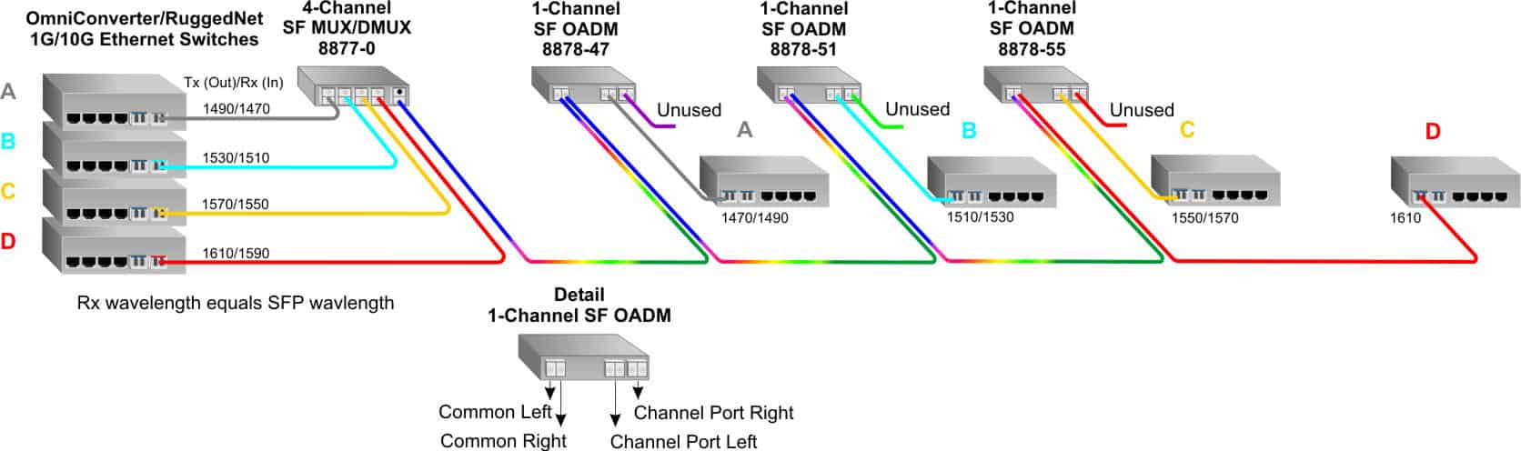
Linear Add/Drop
In this application, 1-Channel SF OADMs and a 4-Channel SF MUX/DEMUX module creates a linear network dropping services off to four sites on a single-fiber common link.
At the headend, a 4-Channel single-fiber MUX/DEMUX is used to connect four Ethernet switches each supporting two wavelengths over a common fiber link. At the first site, a 1-Channel OADM is installed to remove and add the 1470/1490nm wavelength which is associated with Network A. The remaining wavelengths (1510/1530nm, 1550/1570nm and 1590/1610nm) are passed through the OADM to the next site.
The 1510/1530nm wavelength associated with Network B is dropped at the second site while the 1550/1570nm and 1590/1610nm wavelengths are passed on to the last two sites. The 1550/1570nm wavelength associate with Network C is dropped at the third site. Since only 4 channels are used, the last site does not need a OADM module.
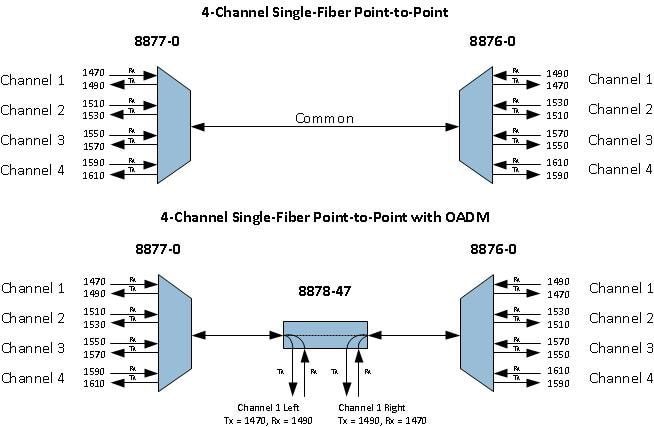
Basic Application Diagrams
Below are block diagrams representing a 4-Channel CWDM Single-Fiber point-to-point application and a 4-Channel CWDM Single-Fiber point-to-point with an OADM somewhere in between the 4-Channel MUXs.
All Single-Fiber modules have dual fiber channel ports and single-fiber common ports. The CWDM SFP transceiver required for any single-fiber application depends on the Rx wavelength of the Single-Fiber module.
In the 4-Channel point-to-point diagram below, the CWDM SFP transceiver wavelength needed for Channel 1 of the 8877-0 module is 1470nm.
In the 4-Channel point-to-point with OADM, the CWDM SFP transceiver wavelength needed for the OADM Channel 1 Left is 1490nm and for Channel 1 Right is 1470nm.
Step 1: Choose a Base Part Number (xxxx-xt)
| Model Number | Model Type | Channel Port ITU Center Wavelengths (nm) Tx (Out) / Rx (In) |
|---|---|---|
| 8870-0t | 2-Channel MUX/DEMUX with LC UPC Connectors | Channel 1 = 1471/1491, Channel 2 = 1511/1531 |
| 8871-0t | 2-Channel MUX/DEMUX with LC UPC Connectors | Channel 1 = 1491/1471, Channel 2 = 1531/1511 |
| 8872-0t | 2-Channel MUX/DEMUX with LC UPC Connectors | Channel 1 = 1551/1571, Channel 2 = 1591/1611 |
| 8873-0t | 2-Channel MUX/DEMUX with LC UPC Connectors | Channel 1 = 1571/1551, Channel 2 = 1611/1591 |
| 8874-0t | 4-Channel MUX/DEMUX with LC UPC Connectors |
Channel 1 = 1271/1291, Channel 2 = 1311/1331,
Channel 3 = 1351/1371, Channel 4 = 1431/1451
|
| 8875-0t | 4-Channel MUX/DEMUX with LC UPC Connectors |
Channel 1 = 1291/1271, Channel 2 = 1331/1311,
Channel 3 = 1371/1351, Channel 4 = 1451/1431
|
| 8876-0t | 4-Channel MUX/DEMUX with LC UPC Connectors |
Channel 1 = 1471/1491, Channel 2 = 1511/1531,
Channel 3 = 1551/1571, Channel 4 = 1591/1611
|
| 8877-0t | 4-Channel MUX/DEMUX with LC UPC Connectors |
Channel 1 = 1491/1471, Channel 2 = 1531/1511,
Channel 3 = 1571/1551, Channel 4 = 1611/1591
|
| 8878-λt | 1-Channel Add/Drop Lower Band with LC UPC Connectors | λ = 27 (1271/1291), 31 (1311/1331), 35 (1351/1371), 39 (1391/1411), 43 (1431/1451) |
| 8878-λt | 1-Channel Add/Drop Upper Band with LC UPC Connectors | λ = 47 (1471/1491), 51 (1511/1531), 55 (1551/1571), 59 (1591/1611) |
|
Single-fiber CWDM/X models must be used in pairs. The Tx wavelengths on one end has to match the Rx wavelengths on the other. For the 1-Channel OADMs, the Channel Port Left wavelengths are shown in the table above. Channel Port Right wavelengths are reversed from Channel Port Left. 1-Channel Lower Band OADM Example: For wavelength 1351/1371, l = 35, 8878-35 1-Channel Upper Band OADM Example: For wavelength 1551/1571, l = 55, 8878-55 Contact Omnitron for other port configurations, extended temperature (-40 to 75°C) and RoHS (5/6) compliant models. See chassis and mounting options at: iConverter Chassis and Mounting Option web page. |
||
Step 2: Choose an Operating Temperature Option (xxxx-xt)
| <leave blank> = Commercial temperature (0 to 50°C) |
| W = Wide temperature (-40 to 60°C) |
Logic Diagrams
iConverter Single-Fiber CWDM/X (Data Sheet)
iConverter Single-Fiber CWDM/X (User Manual)
iConverter Single-Fiber CWDM/AD (User Manual)
8870-0, 8871-0, 8872-0, 8872-0Z, 8873-0, 8873-0Z, 8874-0, 8874-0Z, 8875-0, 8875-0Z, 8876-0, 8876-0-KFP, 8876-1, 8876-1-KFP, 8877-0, 8877-0-KCC, 8877-1, 8877-1-KCC, 8880-1, 8880-2, 8878-27, 8878-31, 8878-35, 8878-39, 8878-43, 8878-47, 8878-51, 8878-55, 8878-59,
